This chapter explains how to use the Page Layout section to print out your plan, elevations, 3D views etc. It also explains how to save your page so it can be emailed direct to a customer.
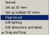
To enter Page Layout mode, click "Mode" - "Page Layout".
Keys used in Page Layout mode.
| Key | Action |
|---|---|
| Delete | Delete the currently selected item. |
| Shift | Hold down "shift" and the left mouse button on a item to rotate - push up/down to rotate. See "Rotation" below. |
| TAB | Cycle through the items on your page. Useful when trying to select an item "behind" another. |
Before starting your page layout, you should choose the paper size, orientation and printer that you wish to use.
NOTE - changing the paper size or orientation after you have started adding items to your page layout can lead to your page not printing correctly.
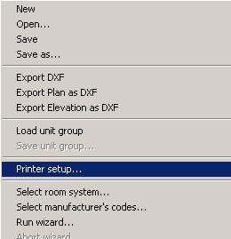
Click "File" - "Printer Setup".
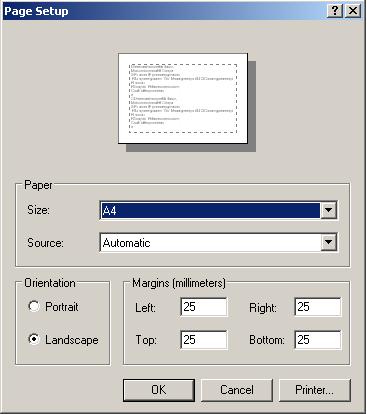
The first time you do a page layout, the printer setup will use the default printer and settings on your system. However, ArtiCAD will remember your selection of paper size and orientation for any subsequent layouts.
Return to top.
All items that can be added to a page layout are created, selected, moved and deleted the same way.
Return to top.
Plan and Elevation items can be drawn to scale. You can specify any scale value. The default is 1:20.
The item will be drawn on the page as it would appear on the currently selected paper i.e. a plan at 1:20 on A4 will appear larger then the same plan, same scale, on A3.
Edit an item to change the scale.
Alternatively, if you wish to do away with the scale option, set the scale value to 0 (zero). This will allow you to resize the item as described below, however it will no longer be to scale.
A selected item has a red box surrounding it. If an item can be resized a black square will appear in each corner. Hold down the left mouse button on a square and drag to the required size.
NOTE - resizing a text box does not change the text size. See "Text and Arrows" for details.
Return to top.
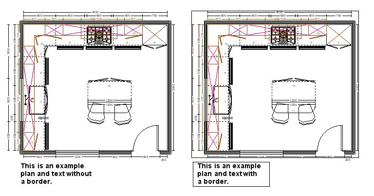
Draws a thin black border around the item.
Return to top.
Once activated, you will not be able to move the item, though you can still resize it. Stops an item being accidentally repositioned.
Return to top.
Items can be rotated two ways.
The same image with the rotation set to 0, 45 and 90.
Return to top.
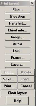
The print layout toolbar holds the buttons used to add items onto your page layout.
To move the toolbar hold down the left mouse button in the bar at the top of the toolbar (where it says "Print Layout") and drag into the required position.
Should you close the toolbar by clicking the "X" in the top-right corner, it can be recovered by clicking "Edit" - "Control Box".
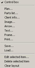
Note that all the options that appear on the toolbar also appear under the "Edit" menu when in "Page Layout" mode.
Return to top.
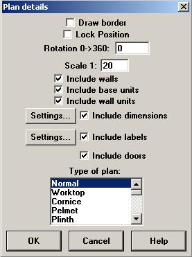
This dialog box is almost identical to the one found under "View" - "Plan options". Changes made to this dialog will only affect the plan you are adding to the page layout.
Draw border, rotation, lock position and scale are covered above.
Click "OK" to add the plan onto the page. Position as described above.
Return to top.
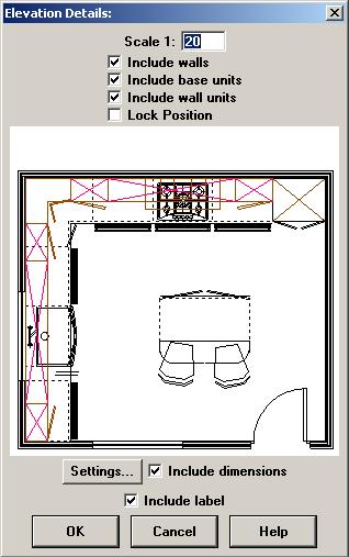
Scale and lock position are covered above.
Select the wall you wish to generate the elevation of. If you do not select a wall, you will get an error "Please select a reference unit.".
Click "OK" to add the elevation onto the page. Position as described above.
For colour elevations, store the image as you would for any other 3D view, then add to the page layout as described in the "Image" section below. See Viewing Your Design for details of storing an image.
Return to top.
Creates a text box containing the current parts list, using the current parts list configuration. See Reports - Parts List for details on configuring the parts list. See also "Frame" below.
Return to top.
Creates a text box containing the client details. See 07 - Set Up Your Design for details of specifying the client details.
Note that it includes all the client details fields, even if nothing is entered in them.
Return to top.
Text and Arrow are usually used together.
Text creates a piece of text that can then be positioned on your page. You can change the font, size and colour of the text and select from a range of pre-defined labels.
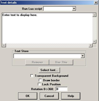
Draw border, rotation and lock position are covered above.
Type the text you want to appear on the page in the box below the "Run lua script" drop down. By default the box is empty, but in the example image above it contains "Enter text to display here."
When you create a text item and add it to the page, the contents of that text item is automatically added to the text store.
To use already stored text click the drop-down arrow and scroll through the list. Left-click on the item on the list you wish to use, then click "Use This" to add into the text box above.
Note that clicking "Use This" will remove any text currently in the text box. However, once the text from the store has been added you can then type additional text into the text box.
To remove unwanted text stored on the list, select the item and click "Remove"
To add the text onto the plan, click "OK". Position as described above.
Arrow allows you to draw a line with an arrow head on the end. Use it to "point" to items on the page. Usually used in conjunction with a text item.
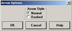
Choose the style of line - solid or dashed. Click "OK" to start drawing the arrow.
Single left-click the mouse where you want the arrow to start, then single left-click where you want the arrow to end. The arrow head is placed at the end.
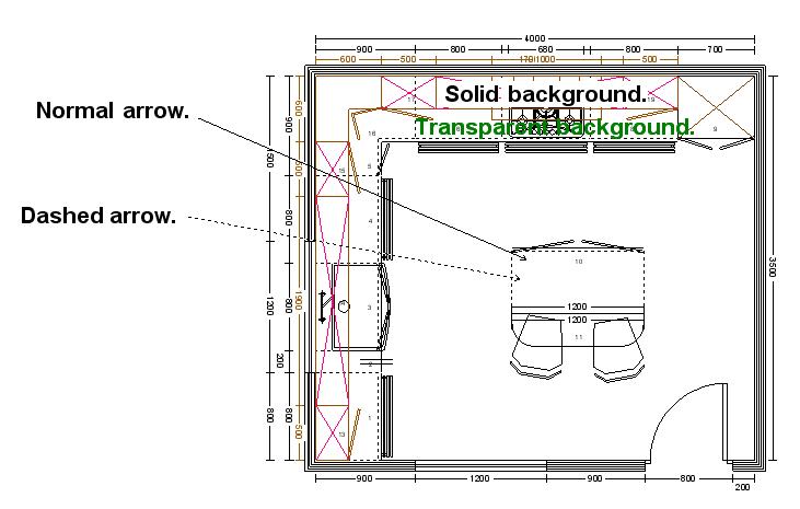
The above image shows the difference between dashed and normal arrows and text with or without a transparent background. The transparent text also has it's colour changed to green to make it easier to see against the plan in the background.
Return to top.
A frame is a template for your page. The frame can be as simple as putting a border around the edge of the page, or adding the current date, or even have your company logo and other pre-defined text built in.
Two frames are included by default - DATE and Standard. Select the one you require from the list and click "OK" to add to your page. See examples below (images are quite large, may take a few seconds to load).
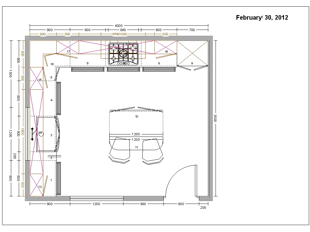
An example plan, 1:40 scale, with the "DATE" frame, on A4.

An example plan, 1:40 scale, with the "Standard" frame, on A4. Note that it has put the parts list, client details and your company details onto the page page.
When using the "Standard" frame, the parts list can sometimes run over the space allocated for it and merge with the client information. Remove the frame and add it again, but try a smaller font, or reconfigure the parts list to have less information. See Reports - Parts List
If you would like your own custom page frame created, please contact Client Care.
Return to top.
Layers allow you to overlay different information onto your page e.g a layer with information for the fitter, another for the plumber and another for the electrician. You can then turn on or off the relevant layer when printing. This keeps all the required information in a single layout.
Move the "Layers" dialog by holding down the left mouse button in the blue bar at the top and dragging to a new position.
Close the "Layers" dialog by clicking the "X" in the top-right corner. Click the "Layers" button on the print layout toolbar to make it re-appear.
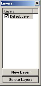
By default your page will have one layer (called "Default Layer").
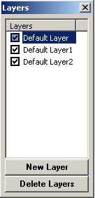
To create a new layer, click "New Layer". The first new layer will be called "Default Layer1", the next "Default Layer2" and so on.
To rename a layer, single left-click on the layer name to select it, then single left-click again. The name will highlight in blue, and you can type your new name.
Visible layers will have a tick beside them. Un-tick to hide the layer.
Adding, moving and editing items works exactly as described above, except you will only affect the currently selected layer i.e. the layer highlighted in blue in the "Layers" dialog.
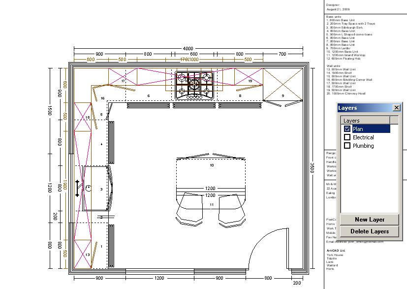
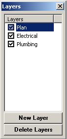
The plan layer contains the frame and the plan.
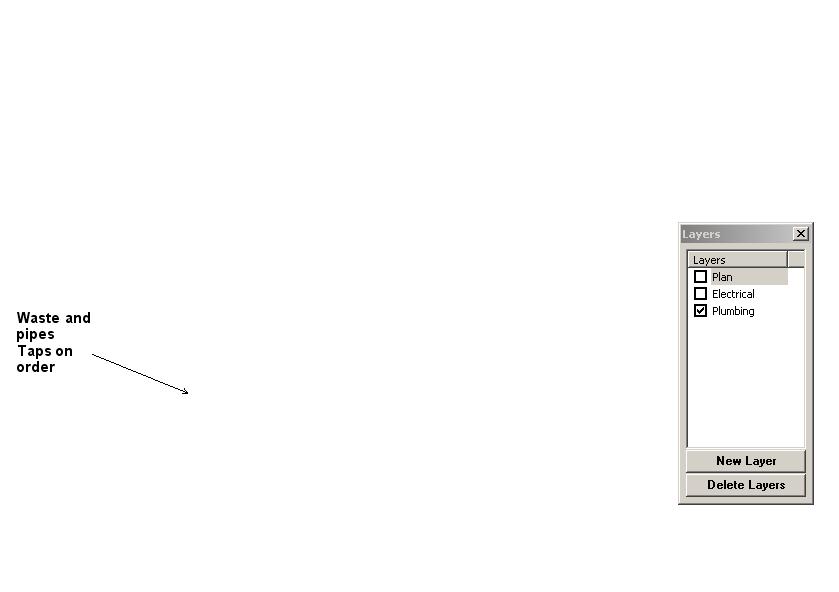
The plumbing layer contains only the text and arrow.
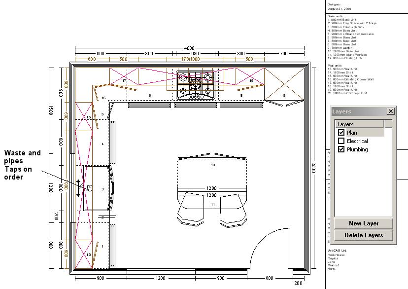
With the plan and plumbing layers active.
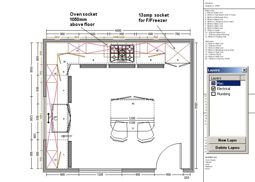
With the plan and electrical layers active.
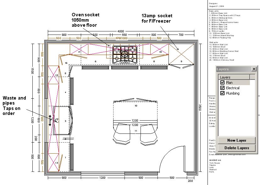
All three layers active.
Layers can also be used to create multiple "pages" within your layout.
In the examples below, the "Frame" layer contains the standard frame, with subsequent layers containing the plan, elevations and images.
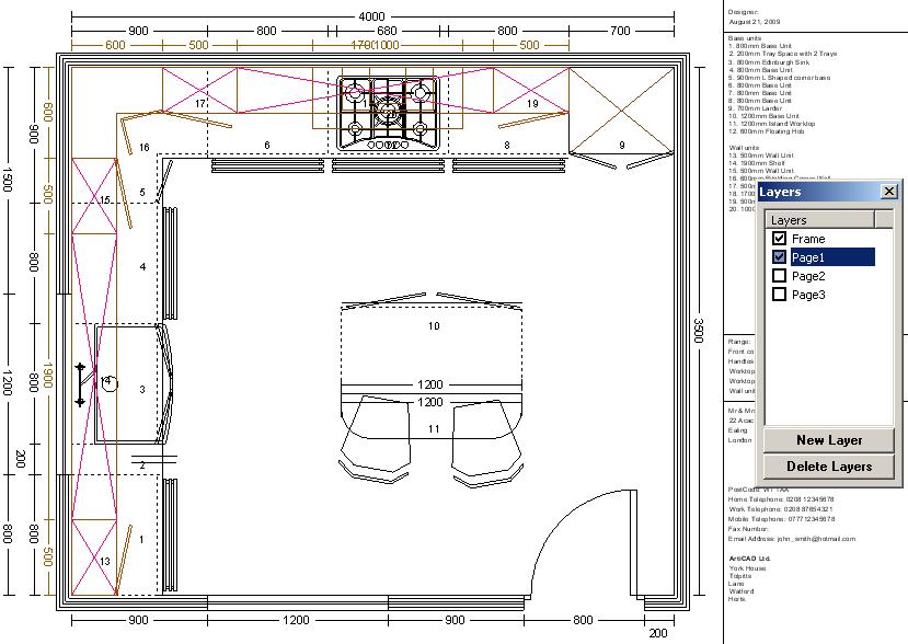
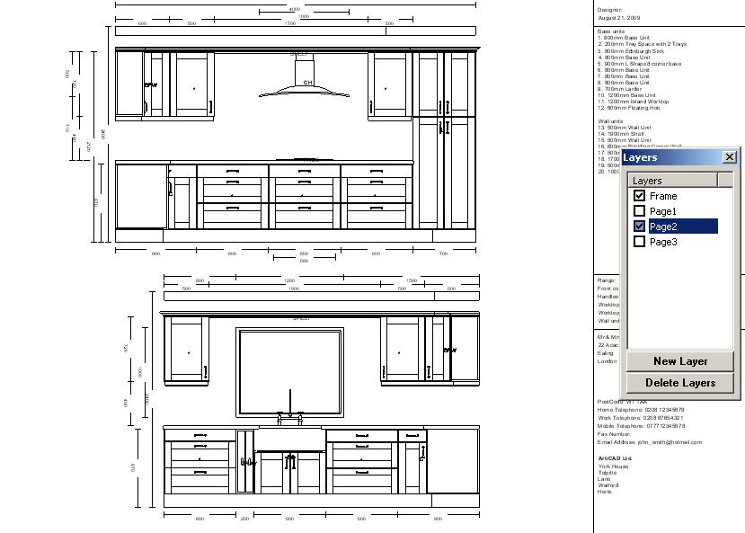
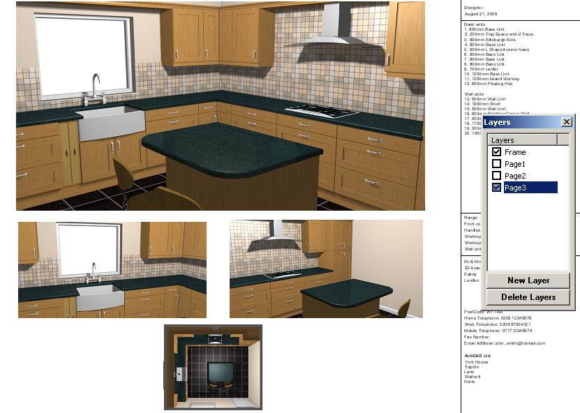
Pressing "Print" will print out the current selected layer(s) as a single page.
Return to top.
Click the "Save" button to save the current state of your page layout. All items and layers will be saved.
By default, your page layout is saved as a Layout file. Only ArtiCAD can read this type of file. However, you can return to a Layout file and move items around, edit text etc. If is recommended you save as a Layout before saving as any other format (see "Emailing" below).
Return to top.
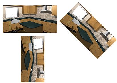
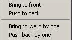
When placing items onto your page they are stacked in the order they are added i.e. the second item is drawn on top of the first, the third item is drawn on top of the second and so on.
To move an item forward/back, right-click on the item.
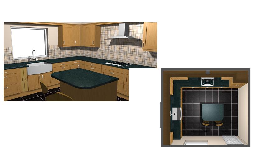
In the above example, the left-hand image was added first and is therefore below the right-hand image. The outline of the second image is overlapping the first and obscuring the bottom-right corner of that image.
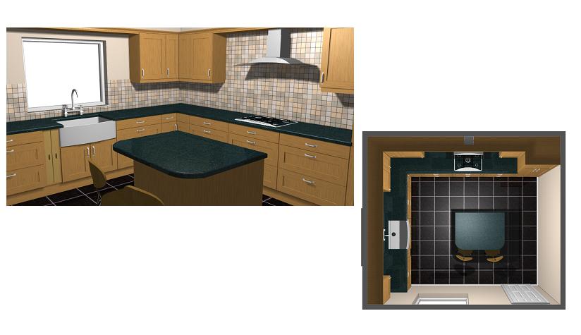
The same image, but with the first image brought to the front. Though it is just as valid to push the second image to the back.
Note that moving an item forward/back changes it's position within the current layer only.
Return to top.
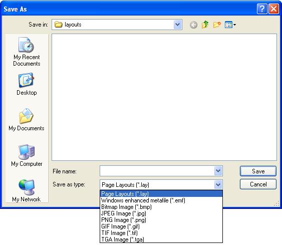
By default, your page layout is saved as a Layout file. Only ArtiCAD can view files of this type. If you wish to email your layout to a customer you need to save it in a format they can view. We recommend the JPEG format as this is the most widely accepted format.
Click the "Save" button on the Print Layout Toolbar.
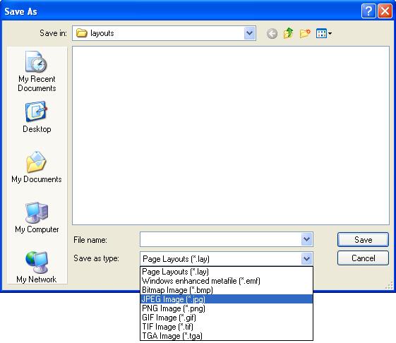
Change the "Save As Type" to "JPEG image (*.jpg)". Name the file as appropriate.
NOTE - only the currently active layers will be saved.
Attach the newly created image to your email as you would any other file. The exact method for attaching the file will depend on your email client. Please consult the documentation supplied with your email client if you are unsure how to attach a file.
Return to top.